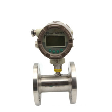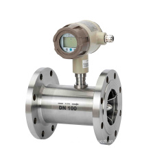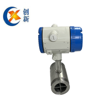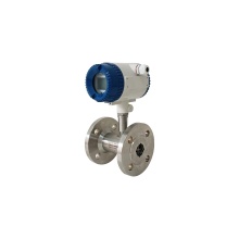


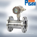
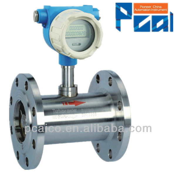
LWGY Liquid turbine flow meter type factory
Basic Info
Model No.: LWGY Series
Product Description
For Liquid (Water, Diesel, Gasoline)
High Accuracy: 1.0% or 0.5% or rate
DN4 to DN200
LWGY Liquid turbine flow meter type SPECIFICATIONS turbine flow meter type
Performance
Repeatability:±0.2%
Accuracy:Standard: ±1% of reading;Optional: ±0.5% of reading
Wetted Components
Housing:Standard - 304 Stainless Steel Optional - 316 Stainless Steel
Bearings and Shaft:Tungsten Carbide
Rotor:Standard - 2Cr13 Stainless Steel
(Optional Alloy CD4Mcu)
Retaining Rings:316 Stainless Steel
Output Signal: (Where applicable)
Sensor:Pulse signal (Low Level: ≤0.8V; High Level: ≥8V)
Transmitter: 4 to 20 mA DC current signal Signal Transmission Distance: ≤1,000 m
Electrical Connections:Basic Type:Hausman Connector or three-core cable
Explosion Proof Type:ISO M20×1.5 Female
Explosion Proof Level:
Standard:None
Optional:ExdIIBT6
Protection Level:IP65
OPERATION CONDITIONS
Ambient:
Temperature:-10°C to +55°C
Pressure:86 to 106 KPa
Relative Humidity:5% to 90%
Power Supply:
Sensor:+12V DC (Optional: +24V DC)
Transmitter:+24V DC
Field Display Type B:
Integral 3.2V Lithium Battery (Others available on request)
Field Display Type C:
+24V DC
Fluid Temperature and Pressure:
Temperature:
-20°C to +110°C
Pressure:
Fluid pressure should be limited according to rating. Datasheet for optional :
|
|
|
|
| Description | ||||
Type | A |
|
|
|
| Flow sensor pulse output three-wire system, +12V power supply; | |||
B |
|
|
|
| Local display, powered by 3.6V battery; | ||||
C |
|
|
|
| Local display with 4~20mA or pulse output, powered by 24V; | ||||
D |
|
|
|
| Flow transmitter 4~20mA output, powered by ,24V; | ||||
Nominal drift diameter | 4 |
|
|
| Normal flow range m3/h | 0.04~0.25 | Extended flow range m3/h | 0.04~0.4 | |
6 |
|
|
| 0.1~0.6 | 0.06~0.6 | ||||
10 |
|
|
| 0.2~1.2 | 0.15~1.5 | ||||
15 |
|
|
| 0.6~6 | 0.4~8 | ||||
20 |
|
|
| 0.8~8 | 0.45~9 | ||||
25 |
|
|
| 1~10 | 0.5~10 | ||||
32 |
|
|
| 1.5~15 | 0.75~15 | ||||
40 |
|
|
| 2~20 | 1~20 | ||||
50 |
|
|
| 4~40 | 2~40 | ||||
65 |
|
|
| 7~70 | 3.5~70 | ||||
80 |
|
|
| 10~100 | 5~100 | ||||
100 |
|
|
| 20~200 | 10~200 | ||||
125 |
|
|
| 25~250 | 12.5~250 | ||||
150 |
|
|
| 30~300 | 15~300 | ||||
200 |
|
|
| 80~800 | 40~800 | ||||
Explosion protection |
|
|
| Not marked, without explosion protection | |||||
B |
|
| Explosion protection type | ||||||
Precision class | A |
| Precision: Class 0.5 | ||||||
B |
| Precision: Class 1.0 | |||||||
Turbine type | A | Normal flow range | |||||||
B | Extended flow range | ||||||||
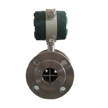
| Note: Sensors with pipe diameter of DN4~DN40 are of thread connections with maximum operating pressure of 6.3Mpa. Sensors with pipe diameter of DN50~DN200 are of flange connections with maximum operating pressure of 2.5Mpa. Sensors with pipe diameter of DN4~DN10 are provided with front and rear straight pipe sections and filters. Please specify when placing an order if flange connections are required for pipe diameter of DN15~DN40. Please specify when placing an order for high pressure type and special requirements. | |||||||||
 Contact us if you need more details on Turbine Flow Meter Type. We are ready to answer your questions on packaging, logistics, certification or any Other aspects about Turbine Flow Meter Type、Turbine Flow Meter Type. If these products fail to match your need, please contact us and we would like to provide relevant information.
 Product Categories : Turbine Flow Meter
Premium Related Products